Linsn Led studio RCG file intelligent setup
02.06.2020 updated
Linsn Intelligent Setup full guide.
Before starting intelligent setup, you must make sure your equipment is working properly. Look at your sender and receiving card. The red and green diodes should be bright on the sender card. The red diode should light up on the receiving card and the green diode will flashing if your receiver card working normally. This means that the signal from the videocard normally enters to your control system.
If the cards do not work normally, change the connecting wires to others. Replace dvi hdmi or ethernet between devices of your control system. If after replacing the wires your cards continue to work incorrectly, try updating the firmware of the cards or replace them.
Step one. Install correct software for linsn control system.
Download and install the right software to setup your screen settings. Use the official website https://linsn.com or download the software on our website in the download section.
Do not use any versions of ledset/linsn led studio from other sites. They may contain viruses or may not work correctly.
Step two. Run linsn software and go to receiver menu setting.
After starting the program for the first time, make sure that the sender card is detected and working properly.
If the software does not see your sending card, make sure that you have the driver installed correctly.
Also check the usb cable, it must be connected to the card and your computer.

To check the sending card, click the default button and then Check hardware . You should see the card model and firmware version.
Click Save to sender button.
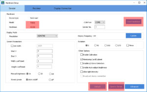
Now go to the receiver menu and press the intelligent setup button.

Step three. Set correct parameters from your led module.
1.Get data about your led module. Look at these modules and compare with yours.
Full color real pixel module:

Full color virtual pixel module:


Full color DIP led module:
![]()
![]()
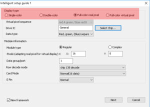
Today, most standard led modules have a full color pixel diode. Set this parameter.
If your module has a virtual pixel or it is not full-color, set another parameter according to your module.
2. Get IC names on the module board.
Get IC names on the module board. On the module are microchips that control the operation of the LEDs. There are many different types of microchips and you need to see which ones you have. Some PWM chips(ICN2038S ICN2013 ICN2017) have complex logic, and if they are on the board, you must select the chip that matches yours from the list. If you do not see matches, set the general parameter. This is suitable for most led modules.


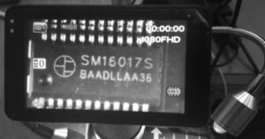
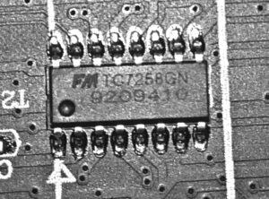


If you see a similar microchip in this list, set it. If not, use the General.
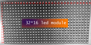
3. Get data about one module resolution.
To make a config file for your screen, you need to know the resolution of one led module. Take the module in your hands and count the number of pixels horizontally and vertically. This is a very important parameter, if you make a mistake, you will not be able to correctly setup the rcg config file. The standard resolution for most led modules are 16 * 8, 16 * 16, 32 * 16, 32 * 32, 64 * 32, 64 * 64.
If you are not sure what resolution the module has, use the standard parameters.
4.Data group/port parameter.

Any LED module can have one or more data groups. One group contains data of three colors, RGB. Look at the hub your module is connected to, a diagram will be drawn on it. If you do not understand which hub you have, or if it has non-standard parameters, use 1. This parameter is suitable for most modules.
For example: this led module has 4 datagroup.

4.Row decode mode.

Any LED module has several different microchips for controlling diodes. The row decoder is one of the chips on the board. If you see an IC name that matches any name from row decode list, you must choose the correct row decoder. For all other cases, set the chip 138 decode. This is a standard chip that fits for most modules.
5.Card mode.

This parameter determines what type of data is used for your receiving card. If you use rv908 cards or the like where no more than six ports are involved, use normal 16. This is also true for older types of receive cards, such as rv 801. If you use all ports of the receiving card, set the parameter 24 data group to enable it.
6.E pin.
Use normal parameter for standart modules, and use other one for double-height modules and anbother non-standart modules.
Step 2 of intelligent setup.
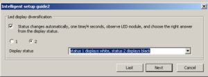
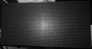
Look at your LED module. If the settings of the previous menu were correct, the module will turn white or black.
If you do not see black / white, check the following:
1) The module must be connected to the first port of the receiving card.
2) The monitor screen should be duplicated(clone mode).
3) Check the location of the contacts on the hub connector.
They must be identical for the hub and module.

Then select the desired mode in the led set menu.
Step 3 of intelligent setup.

Look at your LED module again. In one mode, the diodes should glow brighter than in the other. Select the correct mode from the menu.
If at the previous step, you saw black and white. This will work correctly. If you do not see the differences, maybe you choose wrong IC DRIVER. If you don’t know, select the status one brighter than status two.
Step 4 of intelligent setup.

At this step, you should see switching colors. Select a mode for each color. If you do not see the correct colors, check the information in the previous steps (IC DRIVER first) and the correct connection of the LED hub to the module.
Step 5 of intelligent setup.

In the next step, we need to define a module scan. Look at one module, how many bright lines glow on it. And in the menu, set the number of bright lines. Also you need to set the interval of dim lines between two bright lines and add one line. For example, you see two bright lines on the module and between them three not bright lines. So you need to put two and four. Four, because we added one not bright line.
If you do not see bright lines at this step, or you see distortion in the picture, check the first step of the intelligent setup, and return here again.
Step 6 of intelligent setup.

At this step, we determine the order of the data loaded into the LED driver registers. You should see a blinking dot on your LED module.
Determine the place where the point is and click in the same place in the table. Continue until the process stops automatically.
Sometimes you may not see the LED dot. This is usually due to incorrect settings in the first step. You may also encounter a complex LED module. If your module has an odd scan or resolution that is not a multiple of 16 or 32, you have a complex module. Look at the manual on setting up a complex module on linsn.com or our Facebook group. When the file is formed, move the mouse cursor or the application window to the upper left corner of the screen. If everything is done correctly, you will see a normal image. Next you need to set the parameters of your module and cabinet. Set the required permission according to your cabinet. Also set the refresh rate and gray level. If you do not know what frequencies to set, set scan clock 16.7 and gray level 65536 normal.

Subscribe to our channels: